
- All
- Product Name
- Product Keyword
- Product Model
- Product Summary
- Product Description
- Multi Field Search
Views: 0 Author: Site Editor Publish Time: 2026-10-19 Origin: Site


Thermal regulation dictates the safety and functionality of modern heating appliances. Precise temperature management acts as the primary defense against component failure. It prevents severe fabric damage and eliminates fire hazards. This holds true especially when devices operate unattended. Engineers face a distinct challenge in appliance design. They must balance rapid thermal escalation with immediate, reliable circuit interruption. Maintaining consistent heat cycles without degrading internal components over thousands of uses requires robust engineering. The mechanical and electrical principles behind the electric iron thermostat solve this exact problem. This component architecture relies on fundamental physics to control electrical currents. Evaluating these systems requires a deep understanding of component durability and failure analysis. Repair professionals, product engineers, and component specifiers must analyze these mechanisms to ensure long-term operational safety and performance.
Mechanical Simplicity Drives Reliability: The core of iron temperature control relies on the differential expansion rates of a bimetallic strip, providing a fail-safe mechanical response to electrical heating.
Symbiotic Component Operation: The electric iron heating element and thermostat must be precisely calibrated to work in tandem; the thermostat prevents the heating element from exceeding safe operational thresholds.
Crucial Safety Redundancies: Modern evaluation requires looking beyond the thermostat to secondary safety mechanisms, such as thermal fuses and auto-shutoff timers, to ensure compliance with global appliance safety standards for unattended operation.
Application-Specific Selection: Steam iron temperature control requires different thermal mass considerations and moisture-resistant component housing compared to traditional dry irons.
A baseline thermostat must meet strict success criteria to function safely. It must accurately sense rising heat from the soleplate. It must break the electrical circuit at a precise, predetermined threshold. Finally, it must remake the circuit once the temperature drops below a specific point. All these actions must occur automatically without any manual intervention. Understanding how does an iron thermostat work requires examining its core physical components on the workbench. When you open up a standard unit, you immediately see the mechanical simplicity. There are no complex microprocessors in the primary safety loop. Instead, you find raw metal components designed to react to thermal energy.
The system relies heavily on specific metallurgical compositions. Manufacturers bond two distinct metals together to create the sensing component. One side typically features a high-expansion metal like brass or copper. The opposite side uses a low-expansion metal, usually invar or a specific iron alloy. This bonded strip forms the mechanical brain of the appliance.
Thermal expansion physics drive the entire operation. As ambient heat from the soleplate rises, the two metals absorb thermal energy. The brass or copper expands rapidly. The invar resists expansion. Brass has a linear expansion coefficient of approximately 19 micrometers per meter per degree Celsius, while invar sits at just 1.2 micrometers. This massive differential generates the mechanical force required to snap the heavy electrical contacts apart. If manufacturers use cheaper steel alloys instead of true invar, the differential shrinks, resulting in sluggish contact separation and increased electrical arcing.
This unequal expansion forces the entire strip to bend or curve toward the low-expansion side. The bimetal thermostat in electric iron designs uses this predictable physical curvature to perform mechanical work. We measure this deflection during quality control using dial indicators. A standard brass-invar strip might deflect 0.1mm for every 10 degrees Celsius of temperature rise. This predictable movement allows engineers to calibrate the exact breaking point of the circuit.
The electrical pathway routes directly through a set of contact plates. These plates sit in a normally closed position, allowing current to flow. The physical bending of the bimetallic strip eventually exerts pressure on the upper contact plate. Once the curvature reaches the critical temperature threshold, it forces the upper and lower contact plates apart.
Many high-end thermostats incorporate a beryllium copper snap-spring mechanism. Instead of the contacts slowly drifting apart as the bimetal strip bends, the strip pushes against the snap-spring. Once the spring passes its center of gravity, it violently snaps the contacts open in milliseconds. This rapid separation extinguishes the electrical arc much faster than a slow-break design, drastically extending the lifespan of the silver contact pads.
This separation causes an immediate cessation of current flow. Breaking the circuit stops the heating element from generating more thermal energy. A cooling phase immediately begins. As the soleplate cools, the bimetallic strip loses heat and straightens. The contact plates snap back together, reconnecting the circuit and resuming the heating process.
This mechanical action ties directly to the appliance indicator light. The light wires in parallel with the heating element. It provides the user with immediate visual feedback. When the light illuminates, the thermostat contacts are closed, and active heating occurs. When the light extinguishes, the contacts are open, indicating the cooling phase. On the repair bench, we test this cycle using a multimeter set to continuity. You can physically hear the audible click of the contacts separating and watch the meter drop to zero.
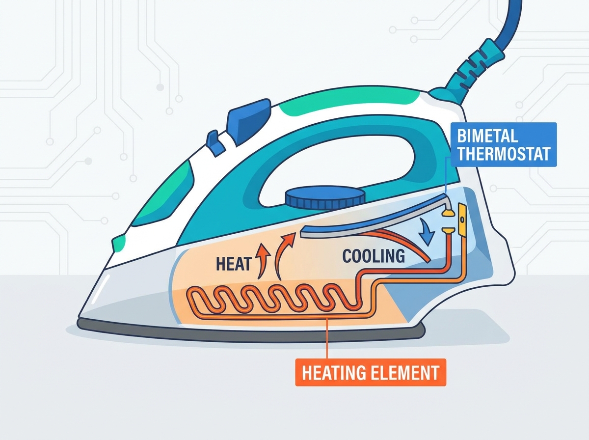
Different heating elements interact uniquely with the thermostat assembly. Most modern designs embed a Nichrome wire directly into a cast aluminum soleplate. The electric iron heating element and thermostat must operate in perfect synchronization. The thermostat acts as the governor for the high-output heating coil.
Resistance heating converts electrical energy into thermal energy rapidly. The Nichrome wire resists the flow of electricity, generating intense heat almost instantly. A standard unit pulls between 1200 and 1800 watts. The Nichrome wire is never exposed directly to the air. It is packed tightly inside a steel or copper tube filled with magnesium oxide powder. Magnesium oxide acts as an excellent thermal conductor but a terrible electrical conductor. This allows the heat to transfer rapidly to the aluminum soleplate while keeping the live electrical current safely isolated. The thermostat mounts directly to a raised boss cast into this aluminum soleplate to ensure the most direct thermal path possible.
This rapid conversion explains why an automated regulator remains strictly necessary. Without intervention, the element would continue heating until it melted the surrounding casing or ignited nearby materials. Runaway heating presents a severe structural and safety risk.
Engineers must account for thermal lag in their designs. Thermal lag represents the delay between the heating element generating heat, the thick aluminum soleplate absorbing it, and the thermostat finally sensing it. The thermostat must anticipate this lag. It often cuts power slightly before the soleplate surface reaches the absolute target temperature, allowing residual heat to carry the surface to the correct level. We map this thermal lag using infrared thermometers during the prototyping phase. A poorly calibrated unit will overshoot the target temperature by 20 degrees or more, scorching fabrics instantly.
The user-adjustable temperature dial controls the mechanical feedback loop. This dial connects to a threaded shaft or a cam mechanism directly above the thermostat assembly. Turning the dial physically alters the resting distance between the contact plates or changes the initial tension applied to the bimetallic strip.
Adjusting the dial changes the physical requirements for breaking the circuit. Setting the dial to a high heat setting increases the tension on the strip. The strip must absorb significantly more heat and bend further to separate the contacts. Setting the dial to a low heat setting reduces the tension. The strip requires minimal heat to bend and break the circuit. This mechanical calibration allows one appliance to safely press highly sensitive synthetics and heavy natural fibers. When calibrating these dials on the assembly line, technicians use precise torque screwdrivers to set the baseline tension. Even a quarter-turn off can shift the entire temperature range by 15 degrees.
Evaluating thermal dynamics requires comparing dry heating systems against those managing water vaporization. Dry irons deal with a relatively stable thermal mass. Steam irons introduce a volatile cooling agent directly into the heated environment. Proper steam iron temperature control demands distinct engineering solutions. You cannot simply drop a dry iron thermostat into a steam unit and expect it to perform.
Steam generation creates sudden, severe temperature drops. When cold water drips from the reservoir into the heated steam chamber, it absorbs massive amounts of thermal energy to flash-vaporize. This process rapidly cools the surrounding soleplate. The thermostat must detect this sudden drop immediately.
Steam iron thermostats require calibration for faster recovery times. Engineers refer to this as maintaining a tighter hysteresis loop. The thermostat must reactivate the heating element much faster than a dry iron equivalent. If the recovery time lags, the soleplate temperature drops too low. This results in water leaking or spitting from the steam vents instead of vaporizing. Consistent soleplate temperatures remain mandatory during heavy steam output. We test this by running the unit at maximum steam output for ten minutes straight while monitoring the soleplate temperature with thermocouples. The temperature graph should show tight, rapid waves rather than deep, slow valleys.
Introducing water into an electrical appliance requires aggressive component protection. The bimetallic strips and electrical contacts face constant threats from steam ingress. Moisture causes rapid oxidation on raw metal surfaces. Mineral buildup from hard water can coat the bimetallic strip, altering its thermal expansion properties.
The thermostat also works in tandem with the steam drip valve. The valve uses a secondary bimetal disc that physically blocks water from entering the steam chamber until the soleplate reaches at least 150 degrees Celsius. If the main thermostat fails to reach this temperature, the drip valve remains closed, preventing the iron from leaking cold water all over the ironing board.
Engineering requirements dictate specialized housings. Thermostat assemblies in steam irons often feature protective shields or conformal coatings on non-contact surfaces. The contact points themselves must resist corrosion. Proper sealing prevents steam from bridging the electrical gap, which could cause a short circuit or premature component failure. During teardowns of failed units, we frequently find heavy calcium deposits bridging the contact plates. This happens when the manufacturer cuts corners on the silicone gaskets isolating the steam chamber from the electrical housing.
Engineers and procurement teams need a strict framework when evaluating thermostat components. Whether sourcing for new manufacturing lines or bulk repair operations, specific metrics define component quality. Reliable iron temperature control relies entirely on the precision and durability of these sourced parts. You must look past the spec sheet and understand how the component behaves under load.
Hysteresis defines the acceptable temperature variance between the cut-off point and the cut-in point. A thermostat might cut power at 200 degrees Celsius and restore power at 190 degrees Celsius. This 10-degree gap represents the hysteresis band. Procurement teams must evaluate the trade-offs associated with this variance.
A tight tolerance creates a narrow band. The iron maintains a highly accurate temperature. However, this requires frequent switching. Frequent switching accelerates mechanical wear on the bimetallic strip and increases electrical arcing at the contacts. A loose tolerance reduces switching frequency and extends component life. Unfortunately, it causes wider temperature fluctuations, leading to a poor user experience and potential fabric damage. Finding the sweet spot usually means specifying a hysteresis band of around 12 to 15 degrees for standard consumer units.
Contact point lifespan dictates the overall longevity of the thermostat. During the break phase, electricity attempts to jump the widening gap between the plates. This creates a momentary electrical arc. Arcing generates extreme localized heat, which can pit or melt standard metals.
Manufacturers must specify high-grade materials to combat arcing. Silver alloys or specialized tungsten-silver composites serve as the industry standard for contact points. These materials resist pitting and maintain high electrical conductivity even after thousands of heating cycles. Inferior contact materials lead directly to premature appliance failure. We run accelerated life testing on these contacts, cycling them 100,000 times under full electrical load. Cheap copper contacts usually weld shut before hitting the 10,000-cycle mark.
Modern safety standards prohibit relying solely on a bimetal thermostat. Mandatory integration of a thermal fuse provides a critical fail-safe. If the thermostat contacts weld together, the appliance will heat uncontrollably. The thermal fuse sits in series with the main power line, mounted directly to the soleplate.
Standard thermal fuses used in these applications are typically rated between 240 and 300 degrees Celsius, depending on the maximum wattage of the heating element. They use a specialized wax pellet that melts at the exact rated temperature, releasing a spring that permanently breaks the internal wire. Once blown, you must replace the entire fuse assembly using high-temperature crimp connectors, as soldering would instantly melt the new fuse.
If the soleplate exceeds a catastrophic temperature threshold, the thermal fuse permanently breaks the circuit. This is a one-time, non-resettable event designed strictly to prevent fires. It ensures compliance with UL and CE safety standards. Advanced designs pair bimetal thermostats with electronic tilt-switches and timers. These systems monitor the physical position of the appliance. If left horizontal and motionless for 30 seconds, or vertical for 8 minutes, the electronic timer cuts power via a secondary relay. This adds a vital layer of safety for unattended operation, entirely independent of the mechanical thermal regulation.
Component degradation remains an unavoidable reality in high-heat applications. Diagnosing these failures requires understanding the physical stress placed on the thermostat assembly over time. Field technicians see the same failure patterns repeatedly.
Contact welding stands as the primary cause of severe overheating. Repeated electrical arcing vaporizes microscopic amounts of metal. This process leaves behind carbon deposits on the contact plates. Carbon increases electrical resistance, generating even more heat at the connection point.
Eventually, the localized heat melts the contact surfaces, fusing them together. The bimetallic strip bends, but it lacks the physical strength to tear the welded contacts apart. The circuit remains permanently closed. Mitigating this risk requires specifying higher-rated contact materials during design. Advanced industrial designs sometimes integrate arc-suppression capacitors to minimize the spark during the break phase. When repairing a unit, you can spot carbon buildup easily. The contacts look black and pitted instead of shiny and smooth. While you can file them down temporarily, replacement is the only permanent fix.
Repeated thermal cycling induces metal fatigue. The bimetallic strip bends and straightens thousands of times over its operational life. This constant mechanical stress alters the crystalline structure of the bonded metals. The strip begins to lose its original tension.
This fatigue leads to calibration drift. The strip may require higher temperatures to achieve the same degree of curvature. The appliance begins running hotter than the dial indicates. Establishing strict QA testing protocols for thermal fatigue during the component sourcing phase mitigates this risk. Manufacturers must test sample batches through tens of thousands of cycles to verify long-term stability. You can diagnose calibration drift by measuring the soleplate temperature at the lowest setting. If it boils water instantly, the strip has lost its tension.
Before replacing the entire assembly, follow these diagnostic steps:
Unplug the appliance and allow the soleplate to cool completely to room temperature.
Disassemble the housing to expose the thermostat assembly and heating element terminals.
Set a digital multimeter to the continuity or resistance setting.
Place the multimeter probes across the main thermostat contact plates.
Rotate the temperature dial from the lowest to the highest setting, listening for the mechanical click and watching for the meter to show continuity.
If the meter shows infinite resistance at all dial settings, the contacts are burned out or the bimetal strip is permanently deformed.
Failure Mode | Root Cause | Operational Impact | Engineering Mitigation |
|---|---|---|---|
Contact Welding | Severe electrical arcing and carbon buildup melting the contact surfaces. | Runaway heating; thermostat fails to break the circuit. Triggers thermal fuse. | Specify silver-alloy contacts; implement arc-suppression mechanisms. |
Calibration Drift | Metal fatigue in the bimetallic strip from repeated thermal cycling. | Appliance runs consistently hotter or colder than the dial setting indicates. | Enforce strict QA thermal fatigue testing; utilize high-grade invar/brass bonding. |
Moisture Ingress | Steam penetrating the thermostat housing, causing oxidation. | Erratic temperature control; potential short circuits across contact plates. | Apply conformal coatings; design sealed or shielded thermostat housings. |
Thermal Lag Imbalance | Poor thermal transfer between soleplate and thermostat mounting point. | Severe temperature overshoot before the thermostat reacts. | Optimize soleplate casting thickness; ensure flush mounting of the thermostat assembly. |
To ensure safe and reliable appliance operation, implement the following component evaluation and testing procedures:
Review component specification sheets to verify silver-alloy contact materials and precise hysteresis bands before bulk ordering.
Conduct extensive thermal cycle testing on sample batches to identify potential calibration drift or metal fatigue early in the design phase.
Verify all secondary safety systems, including thermal fuses and electronic auto-shutoff relays, meet regional UL or CE certifications.
Inspect steam appliance designs to ensure adequate silicone shielding and moisture resistance for the thermostat assembly.
Establish a baseline continuity testing protocol for assembly line workers to catch defective bimetal strips before final casing assembly.
A: The thermostat uses a bimetallic strip made of two different metals. As the soleplate heats up, the metals expand at different rates, causing the strip to bend. At a specific temperature, this bending physically separates two electrical contacts. This breaks the circuit, cutting power to the heating element and preventing overheating.
A: It acts as the primary automated switch for the appliance. It ensures the iron operates strictly within safe thermal limits based on the user's selected fabric setting. This mechanical regulation prevents fabric damage and fire hazards, especially if the device is left unattended for short periods.
A: This indicates normal operation. It represents the feedback loop of the heating element and thermostat maintaining a consistent temperature. The thermostat cuts power when the target heat is reached and restores power when the soleplate cools. This cycle is usually indicated by the appliance's indicator light turning on and off.
A: Steam irons must account for the sudden thermal drop caused by cold water vaporizing into steam. This requires faster thermostat reaction times, known as a tighter hysteresis loop, to maintain consistent heat. Additionally, the thermostat components must be sealed or shielded to resist moisture and oxidation.
A: Thermostats typically fail in two ways. If it fails open, the contacts never touch, resulting in no heat. If it fails closed, the contacts weld together, causing runaway heating. In a closed failure, the backup thermal fuse will permanently cut power to prevent a fire.
A: While technicians can sometimes clean carbon buildup off contact points, it is not recommended. Calibration drift caused by metal fatigue cannot be repaired. Standard industry practice requires replacing the entire thermostat assembly to ensure operational safety and maintain compliance with appliance standards.


